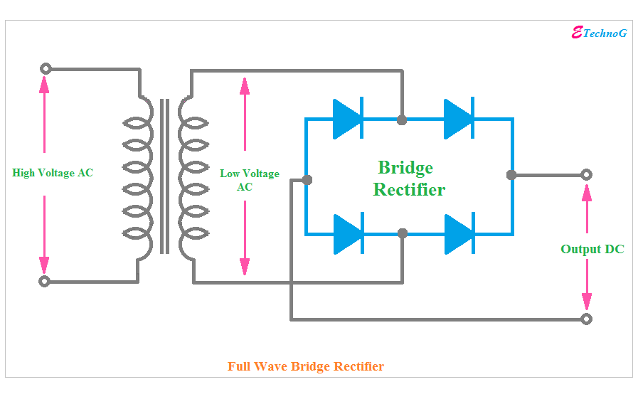
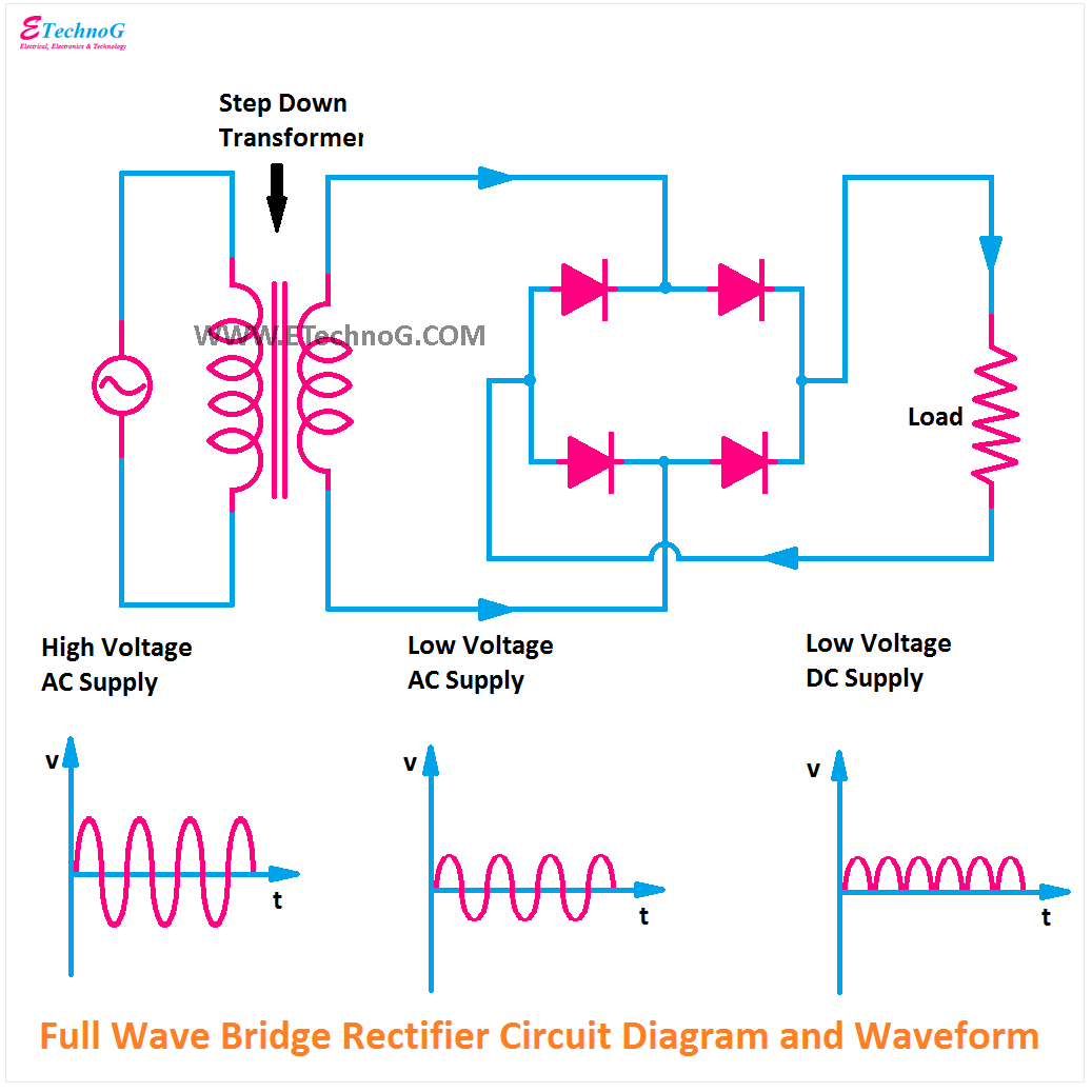
Full Wave Bridge Rectifier Diagram
Rectifier circuit diagram wave output waveform input Full wave bridge rectifier – circuit diagram and working principle Full wave bridge rectifier
Full Wave Bridge Rectifier Circuit - PCB Designs
Rectifier circuit diagram Full wave bridge rectifier circuit Full wave bridge rectifier circuit
Full wave bridge rectifier supply
Rectifier bridge wave supply micro diagram digital detailRectifier waveform capacitor circuitglobe resistor pcb advantages Full wave bridge rectifier – circuit diagram and working principleRectifier bridge diagram circuit wave construction principle working.
Rectifier diode circuitsRectifier principle Schematic diagram of full-wave bridge rectifier.Rectifier bridge wave circuit diagram diode voltage operation peak fig its shown below inverse value when negative.

Rectifier circuit bridge diagram wave working theorycircuit electronics details previous post
.
.


Full Wave Bridge Rectifier – Circuit Diagram and Working Principle

Schematic diagram of full-wave bridge rectifier. | Download Scientific

Full Wave Bridge Rectifier – Circuit Diagram and Working Principle

Full Wave Bridge Rectifier - its Operation, Advantages & Disadvantages

Full Wave Bridge Rectifier Circuit

Full Wave Bridge Rectifier Supply | Micro Digital

electromagnetism - Bridge full wave rectifier more smooth signal